UTILITY POLE MAGIC!
Program Summary & Showcase
Completed: October, 2019
This program creates an elevation view of a utility pole with call-outs, leaders, labels, and dimensions. It makes use of a bit of math to adjust scaling for legibility when needed, as well as dialogue windows to allow for quick and convenient data entry.

VIDEO DEMO
This is a fairly run-of-the-mill pole design. The previous method for drawing these poles would be a marvelous flurry of copy-paste, lines, text-alignment, multileaders, stretching, offsets, etc. The most seasoned in the department might be able to slap this together in 5-10 minutes. Here, I take a stroll while filling out the data and waltz across the finish line at around 3 minutes!
PROGRAM GOALS
The project proposal that granted me nearly a month to learn AutoLISP!
SCALING & SPACING
For the purpose of plotting, drawings must be scaled:
Vertically - 4.5 units: 1 foot
Horizontally - 5.0 units: 1 foot
In the event that pieces of equipment are mounted too closely to be neatly shown on paper, the items shall be spaced vertically 8 units apart. [First coding hurdle!!!!]
Concerning text labels for down guys [the tethering that offsets the tension from the spans of overhead cable]:
If down guys intersect the text, replace the aligned text with a multileader. [Second coding hurdle!!!!]
Each anchor must have a dimension showing the distance from the base of the pole to the anchor point. Each successive dimension should be offset by 7 units to avoid overlap.
FORMATTING
Call-outs:
Text placed to the right of equipment must be left aligned and placed on a line extension.
Text placed to the left of the pole must be right-aligned and placed on a line extension.
In order to minimize/eliminate the need for post-program-formatting, there should be some sort of control within the program for mirroring the blocks & text. [Hurdle!!! - Mirrored text will not stay nicely aligned.]
Call-out line must extend towards the equipment and end 7 units away from the apparent intersection.
Text Content:
For convenience, remove the need for users to re-type heights. Labels should follow this format: [user-defined text] @ [ft]'[in]"
Omit inches if 0.
ADDITIONAL FEATURES
Block selection, user-defined list population:
Populate a drop-down menu with all blocks within the drawing
OR. Enable user-selection of blocks to include in the drop-down menu.
Enable editing of this list without requiring a new AutoCAD session.
Settings Menu!
Enable scaling, text heights, offsets, multileader settings
Enable changing the number of equipment entries
Change text color to index color 90 if the text includes "in:" [install]
Second window should automatically adjust its layout based on the number of non-blank entries in the first user-interfacing window.
RESULTS - SCALING & SPACING

EQUIPMENT SPACING
Shown on the left: early into this project, the program would output this cluster of text and blocks if fed heights that were too close to each other.
Show right: Properly adjusted spacing.
Solution: In the milliseconds between the moment the user hits the "OK" button and the moment the program begins drawing lines and inserting blocks, the program compiles all of the relevant data into a single master-list (user input height [ft], [in], block name, flip/mirror, text label, model space coordinates, etc...). A few lines are spent comparing relative heights and readjusting/substituting values that might be too close. Because the spacing is being stretched for aestheticism and not to scale, a distinction is made between the height that is written in the label, and the actual stretched distance.

LABELS OR MULTILEADERS?
Shown: Examples of spacing and aligned text vs multileader usage.
The goal is to mathematically determine whether the text has enough space, including empty space surrounding it as a border, to be placed on the line. There are a few key AutoLISP functions at work here.
textbox: this function returns information regarding the length in drawing units of the text. This length accounts for the font, skewing, or rotation of the text and allows a boundary to be defined.
vla-intersectwith [acextendthisentity]: to define the boundaries of the text, a circle is drawn at the center of the text, with diameter equal to the text length. This function returns the endpoints of the text without needing to code any trig. Intersecting the circle enclosing the text with the line on which it rests yields the endpoints.
vlax-curve-getclosestpointto: this function churns through a list of all the preceding down guys and produces a list of its own containing perpendicular distances. It is this list that determines whether a multileader or aligned text is appropriate.
RESULTS - FORMATTING

FORMAT!
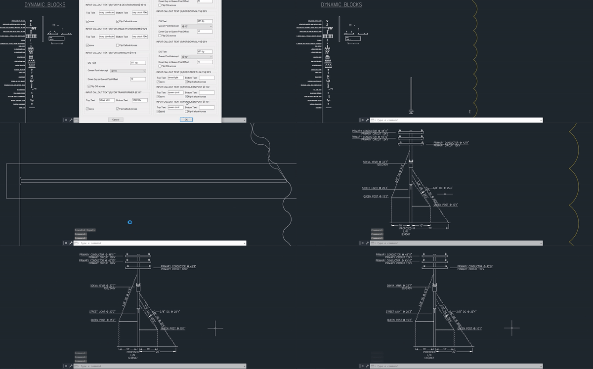
Shown: an example of the program's output. A few minor adjustments would be needed to clean up the aligned text on the down guys. The pole is otherwise ready to be sent to QC.
RESULTS - ADDITIONAL FEATURES

BLOCK SELECTION
Shown: Defined command function "SetBlockList" which allows the user to append blocks to an already existing list, create an entirely new list, remove blocks to lessen the clutter of an overwhelming number of selections, or include every block available within the drawing.

SETTINGS MENU
Shown: the settings menu! Self explanatory - this DCL outputs string-type values. These values are converted to int/real-type where necessary and take priority over default values when defined by the user.
The settings menu also includes a default function to reset all values.

INTERFACE ADJUSTMENT
Shown: 3 columns organizing 13 equipment entries. The DCL window adjusts based on the number of non-null entries.
Update: 12/6/19
A different office for the same company requested that I modify the program to be additionally compatible with a different set of standards. This office uses more simple representations of equipment. Below is the a partial clipped of a demo utilizing the updated interface and settings.
